
The OSI model
The OSI model (Open Systems Interconnection)
| PublishedAug 12, 2026 | Read time12 min | Views103 | Category Networking | Tags — |
The OSI model (Open Systems Interconnection) is a 7-layer framework used to understand how data travels from one device to another over a network.
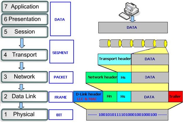
The 7 OSI layers
| Layer | Name | Main job | Examples |
|---|---|---|---|
| 7 | Application | Provides network services to applications | HTTP, HTTPS, DNS, SMTP, SSH |
| 6 | Presentation | Data format, encryption, compression | SSL/TLS, JPEG, JSON |
| 5 | Session | Establishes/manages communication sessions | Session management |
| 4 | Transport | Reliable delivery, ports, segmentation | TCP, UDP |
| 3 | Network | IP addressing and routing | IPv4, IPv6, routers |
| 2 | Data Link | Frames, MAC addresses, switching | Ethernet, VLAN, switches |
| 1 | Physical | Sends raw bits over physical medium | Cable, fiber, radio |
Let’s understand it with a real example Suppose you open: https://www.google.com Your computer needs to communicate with Google’s server. Layer 7 — Application Your browser creates an HTTPS request. For example: GET / HTTP/1.1 Host: www.google.com This is where protocols such as HTTP/HTTPS, DNS, SMTP, FTP, SSH operate.
Layer 6 — Presentation The data may be: • encrypted • compressed • converted into a particular format For HTTPS, encryption is handled through TLS. Conceptually: Application data ↓ Encryption / formatting ↓ Data
Layer 5 — Session This layer manages the communication session between applications. Conceptually: Computer A ↕ Communication session ↕ Server B It deals with establishing, maintaining, and terminating communication sessions. In modern TCP/IP networking, Layers 5–7 are often handled together by applications and protocols rather than as three completely separate layers.
Layer 4 — Transport This is a very important layer for troubleshooting. The main protocols are: TCP Reliable communication. Computer A ↓ TCP segment ↓ Computer B TCP provides things such as: • reliability • sequencing • retransmission • flow control • port numbers Example: Source port: 51520 Destination port: 443 Protocol: TCP UDP UDP is faster and connectionless but doesn’t provide TCP-style delivery guarantees. Common uses include: • VoIP • DNS • streaming • real-time applications For your FreeSWITCH / PBX work, UDP is particularly important because SIP and RTP commonly use UDP.
Layer 3 — Network This is where IP addressing and routing happen. Example: PC 192.168.1.10 | ↓ Router 192.168.1.1 | ↓ Internet | ↓ Server 8.8.8.8 The router looks at the destination IP and decides: “Where should I send this packet next?” Protocols include: • IPv4 • IPv6 • ICMP Devices: Router / Layer-3 switch
Layer 2 — Data Link Now we are dealing with the local network. This layer uses MAC addresses. Example: PC IP: 192.168.1.10 MAC: AA:BB:CC:11:22:33 The switch uses MAC addresses to determine where an Ethernet frame should go. Example: PC A | | Ethernet frame ↓ Switch | ├── PC B ├── PC C └── Server Important concepts: • MAC address • Ethernet • VLAN • ARP • Switches • Frames
Layer 1 — Physical This is the actual transmission of bits. For example: 010101010101010101 The bits travel through: • Ethernet cable • fiber • Wi-Fi radio • electrical signals • optical signals Devices/components include: • cables • fiber • connectors • transceivers • hubs • antennas
The most important concept: Encapsulation This is how OSI becomes very useful. When your computer sends data, each layer adds its own information. Imagine sending: HELLO Application HELLO Transport TCP adds a header: [TCP HEADER][HELLO] Network IP adds another header: [IP HEADER][TCP HEADER][HELLO] Data Link Ethernet adds another header/trailer: [ETHERNET][IP][TCP][HELLO][FCS] Physical It becomes bits/signals: 010101010101010101010… This process is called encapsulation.
What happens at the receiving computer? The reverse happens. Physical ↓ Data Link ↓ Network ↓ Transport ↓ Session ↓ Presentation ↓ Application The receiving device removes the appropriate headers. This is called decapsulation. So: SENDER
Application ↓ Presentation ↓ Session ↓ Transport ↓ Network ↓ Data Link ↓ Physical ↓ NETWORK ↓ Physical ↓ Data Link ↓ Network ↓ Transport ↓ Session ↓ Presentation ↓ Application
RECEIVER
A practical example for your network Suppose your VICIdial server is: 192.168.100.20 and your agent PC is: 192.168.100.50 The agent accesses: http://192.168.100.20 The communication can be viewed like this: Layer 7 HTTP ↓ Layer 4 TCP :80 ↓ Layer 3 192.168.100.50 → 192.168.100.20 ↓ Layer 2 MAC Address ↓ Layer 1 Ethernet Cable This is extremely useful when troubleshooting.
How to troubleshoot using OSI This is probably the most useful part of the OSI model for your work. Suppose a PC cannot access your VICIdial server. You can troubleshoot from Layer 1 upward: Layer 1 — Physical Check: Cable NIC Link light Switch port Fiber Wi-Fi Question: Is there a physical connection?
Layer 2 — Data Link Check: MAC address VLAN Switch port ARP Commands: ipconfig /all arp -a Linux: ip addr ip link ip neigh
Layer 3 — Network Check IP connectivity: ping 192.168.100.20 Then: tracert 192.168.100.20 Linux: ping 192.168.100.20 traceroute 192.168.100.20 If the problem is routing, you’re mainly investigating Layer 3.
Layer 4 — Transport Suppose ping works: PC → Server PING works but: http://192.168.100.20 doesn’t work. Now check TCP port 80. Windows: Test-NetConnection 192.168.100.20 -Port 80 For HTTPS: Test-NetConnection 192.168.100.20 -Port 443 Now you’re investigating Layer 4.
Layer 7 — Application Suppose: Ping → OK Port 80 → OK Port 443 → OK but the website still doesn’t work. Then investigate the application: Apache/Nginx PHP VICIdial Database Application configuration Authentication That’s primarily Layer 7.
OSI and your SonicWall TZ470 This is also very useful for the firewall work you’ve been doing. For example: Internet | ↓ [ SonicWall TZ470 ] | ↓ LAN | ↓ VICIdial / PBX / PCs A firewall can inspect traffic at multiple layers. For example: Layer 3 Source IP Destination IP
Layer 4 TCP/UDP Source port Destination port
Layer 7 Application / content identification So if a website is blocked, you can ask: At which OSI layer is the traffic failing? That question makes troubleshooting much easier.
OSI vs TCP/IP In real networking, you’ll also hear about the TCP/IP model. OSI: 7 Application 6 Presentation 5 Session 4 Transport 3 Network 2 Data Link 1 Physical TCP/IP is usually simplified to: Application ↓ Transport ↓ Internet ↓ Network Access A rough mapping is: OSI TCP/IP
Application ─┐ Presentation ├──────────→ Application Session ─────┘
Transport ──────────────→ Transport
Network ────────────────→ Internet
Data Link ───┐ Physical ────┴──────────→ Network Access OSI is mainly a conceptual/troubleshooting model, while the TCP/IP model reflects the protocol architecture used on the Internet.
Easy way to remember the 7 layers
From Layer 7 → Layer 1:
All People Seem To Need Data Processing 7 Application 6 Presentation 5 Session 4 Transport 3 Network 2 Data Link 1 Physical
And for your networking/PBX work, remember these four especially: L1 = Cable / Signal L2 = MAC / VLAN / Switch L3 = IP / Routing L4 = TCP / UDP / Ports Then: L7 = Application
// Comments (0)